
12
B A
A
B
B
A
3.3 KW THROUGH 15 KW UNIT HEATERS 20 KW THROUGH 48 KW UNIT HEATERS
HOW TO DESIGNATE A MODEL:
H
2
H
UH 10
C
A
1
Element Volts
F = 208
H = 240
HF = 240/208
G = 277
P = 480
Phase
1 = 1-Phase
2 = 1 or 3-Ph.
3 = 3-Phase
Motor Voltage
F = 208
H = 240
B = 240 / 208
G = 277
P = 480
Model Series
UH
Element KW Control System
O = None
C = Contactor
R = Relay
Transformer
O = None
A = Included
Control Volts
1 = 24
2 = 120
3 = Element Voltage
4 = 240
Factory Installed Options (use as a suffix on model designation):
S = Summer Fan Switch, F = Fan Delay, D = Disconnect, T = Built-in Thermostat, E = Epoxy Coated
Field Installed Options:
Disconnect Switch, Built-in Thermostat, & Wall / Ceiling Bracket
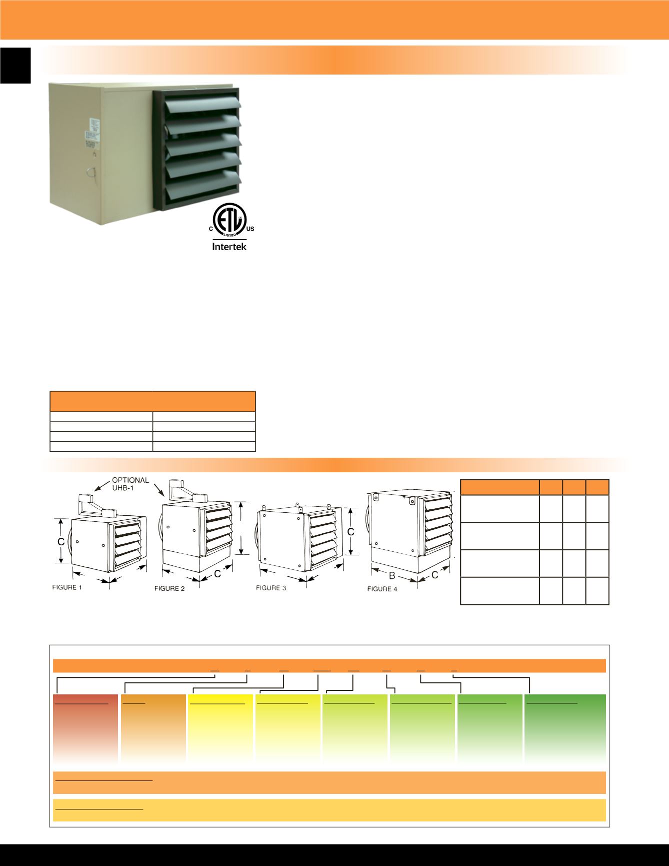
UH Series Horizontal Fan Forced Unit Heater
NOTE:
Louver assembly is square and mounted with
screws. Louver can be removed and repositioned for four
(4) directional air flow - left - right - up - down with the
heater in the horizontal position.
3.3 KW THROUGH 48 KW HORIZONTAL DISCHARGE SUSPENDED FAN FORCED UNIT HEATERS
AVAILABLE IN 1 OR 3 PHASE FOR ALL STANDARD VOLTAGES FROM 208V TO 480V.
Product Dimensions & Model Number Designation
Figures 3 & 4 shown with standard mounting tabs for units over 20 KW. Optional UHB-3 and UHB-4 wall brackets are available. 3.3 KW
thru 15 KW units can be mounted using 1/4” threaded rod. 20 KW thru 48 KW units can be mounted using 5/16” threaded rod.
CONSTRUCTION:
Heavy gauge welded steel cabinet with powder coated finish and control
compartment with a hinged and latched access door, simplifying wiring
installation & maintenance.
HEATING ELEMENT:
Circular copper clad steel sheath element with continuously brazed steel fins
formed to match the air delivery pattern of the fan blade.
OVERHEAT PROTECTION:
All units come equipped with automatic resetting type limit controls to de-
energize the heater should an over-temperature situation occur.
FAN and MOTOR:
Totally enclosed, single phase, permanently lubricated, thermally protected
motors with unit bearings on 3 KW - 10 KW models and sleeve bearings on 12.5
KW - 48 KW models - mounted with rubber insulators to minimize vibration and
noise. Fan assembly enclosed by a heavy gauge, close spaced, chrome plated
wire guard.
LOUVER ASSEMBLY:
Louvers are individually adjustable for directional control of air flow and the
entire assembly can be repositioned in the field from down flow to up flow or
left / right directional air flow.
TEMPERATURE CONTROLS:
20 KW through 48 KW units and all 480V have built in 24 Volt transformer
for low voltage remote thermostat application. 25 KW through 48 KW models
available in 2-stage on special order (consult factory).
INSTALLATION:
Unit Heaters can be mounted with the motor shaft from horizontal to downward
at 45° off horizontal. Pre-drilled holes and installed threaded nuts provided to
allow hanging by threaded rods - 1/4” for units up to 15 KW and 5/16” for 20
KW units and larger. Optional wall / ceiling mounting brackets are available for
all units.
FACTORY INSTALLED OPTIONS:
• 24 Volt transformer on 3 KW to 15KW units to
convert from line voltage to low voltage remote
thermostat operation.
• Summer fan switch to operate the fan only.
• Fan delay switch to purge all residual heat from the
unit after the heating element has cycled off.
• Powder coated epoxy finish for corrosive atmospheres.
• Disconnect switch.
• Made in U.S.A.
Dimensions
A B C
Figure 1:
3.3, 5, 7.5, 10 KW
20” 11” 13”
Figure 2:
12.5, 15 KW
22” 11” 15”
Figure 3:
20, 25, 30 KW
24” 17” 17”
Figure 4:
40, 48 KW
26” 23” 19”
MAXIMUM RECOMMENDED MOUNTING
HEIGHT
3 - 10 KW
9 FT.
12 - 15 KW
10 FT.
20 - 30 KW
13 FT.
40 - 48 KW
16 FT.


