
24
A
A
A
A
B
B
C
C
D
D D
D
D D
W
W Y
Y
Y Z
X
X
X
Z
Completely
Recessed
Semi
Recessed
Completely
Recessed
Semi
Recessed
A
A
W W
W
Y
Y
Y
Y
Z
Z
Z
X
X
X
X
B
C
D
D
D
Completely
Recessed
Semi
Recessed
Up Flow
Down Flow
Ceiling Mounted
KEY:
W
= 6” minimum,
X
= 12” minimum,
Y
= 0” or greater,
Z
= 24” minimum
Product Specifications
NOTE:
Semi-recessed units are to be re-
cessed at a maximum of 3 1/2” unless grill
configuration is front in and front out.
MOUNTING CLEARANCES:
Proper
clearances are indicated for each mount-
ing configuration on all positions. Mini-
mum clearance from side of unit to the
wall is zero inches. Mounting inches are
provided in the back of the cabinet, ac-
cessible through the blower compart-
ment, if necessary, remove blower deck
if additional mounting screws or bolts are
desired. Blower deck may be slipped for-
ward by loosening four screws at the front
to provide access to mounting holes.
Mounting Configurations
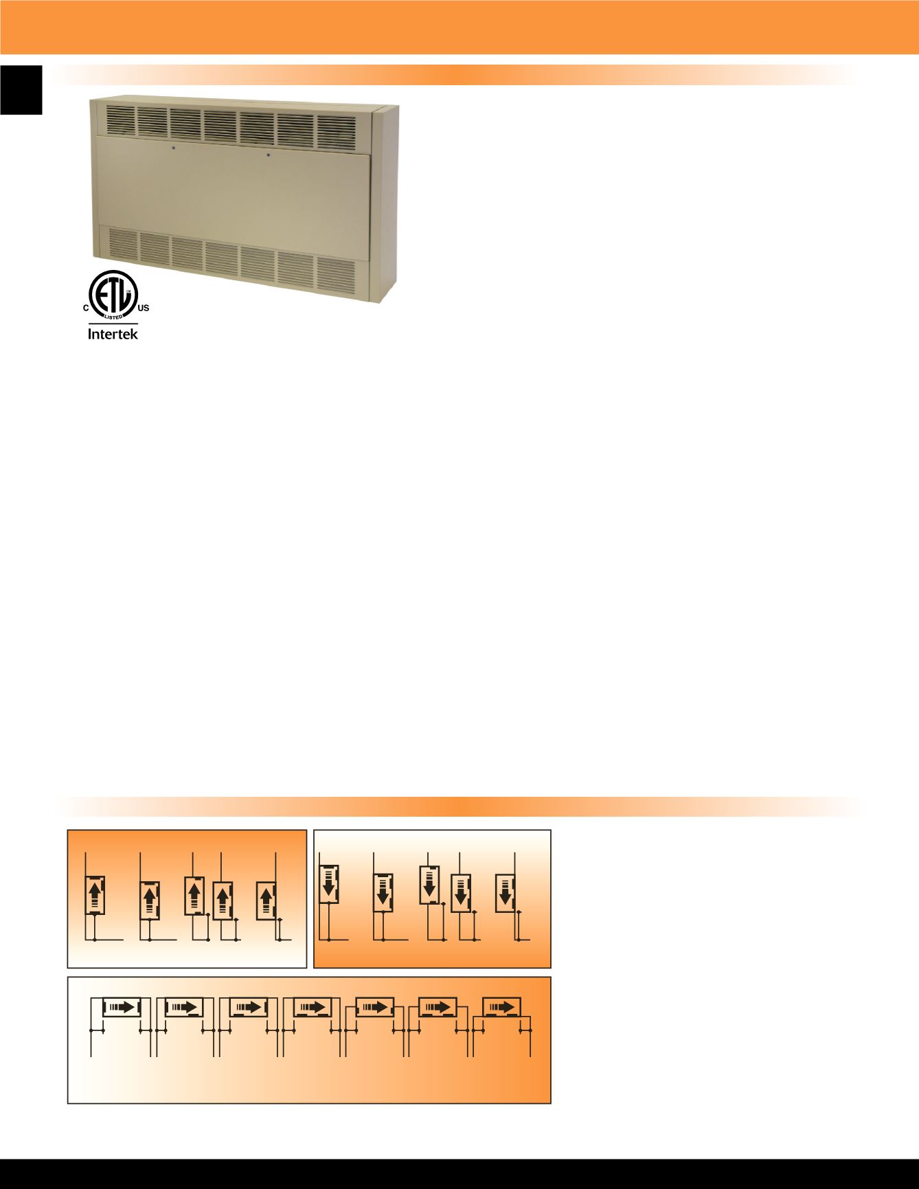
The electric cabinet unit heater is designed for mounting in any
position, fully recessed, semi-recessed or surface mounted. All
capacities, voltages, physical sizes, grille arrangements and options
shall be as specified on the plans. All units must be field convertible
to the following:
1. For control by a field supplied remote thermostat.
2. Load management control with an external dry switch.
When closed unit operates under control of either
the internal or the external thermostat. When open, unit
turns off.
3. Any grille arrangement.
CABINET & CONSTRUCTION:
The cabinet shall be constructed
of heavy duty 16 gauge Zinc coated steel. The heater shall have a
removable front door for easy access to the control panel, elements,
motor-blower assembly, filters and all internal components. The grill configuration must be easily field convertible to any air flow
configuration (by removal of no more than four fasteners). The cabinet shall have a textured finish of two coats of powder coat
epoxy and be suitable for use with optional kick space base. Made in U.S.A.
HEATING ELEMENTS:
The heating elements shall be warranted for 1 year and shall be non-glowing design consisting
of special high temperature resistance wire enclosed in an incoloy sheath to which steel fins are furnace brazed. The heating
elements shall be located directly in front of the blower discharge air for uniform heating. They shall be mounted with a single
anchor at one end to minimize effects of thermal expansion and contraction.
SAFETY CUTOUT:
Thermal safety limits shall be built into the system to automatically shut off heater in event of overheating
due to any cause. The safety cutouts shall be of two types:
A. The primary limit shall be an automatic capillary type to sense the heat along the full length of the heating elements. It shall
de-energize the heaters by opening the coil circuit on the heating contactors.
B. The secondary limit shall be a manual reset thermal device to interrupt power to the heating elements.
MOTOR AND BLOWER ASSEMBLY:
The motors and blowers shall be direct drive and resiliently mounted on rigid heavy
gauge frame for quiet operation and long life. The motor shall be two-speed, shaded pole type, rated for the voltage (480 to 600
Volts are single speed only). Each shall have built-in automatic reset overload protection and are life time lubricated. The motor
shall be vented and mounted in the air stream to provide maximum cooling of the motor.
HIGHAND LOWHEAT RANGES:
All units will be supplied as standard with a switch for selecting full heat at high fan speed
or reduced heat at low fan speed (On 480 & 600 Volt units the switch changes the heat but not the fan speed).
OVER CURRENT PROTECTION:
Circuit breakers shall be provided for branch circuit protection where required by NEC.
Circuit breakers are optional on all other heaters.
TEMPERATURE CONTROL:
Integral factory installed thermostat shall be tamper resistant, linear capillary type.
“T” Series Multiple Angle Cabinet Unit Heater


