12
B A
A
B
B
A
3.3 KW THROUGH 15 KW UNIT HEATERS 20 KW THROUGH 48 KW UNIT HEATERS
HOW TO DESIGNATE A MODEL:
H
2
H
UH 10
C
A
1
Element Volts
F = 208
H = 240
HF = 240/208
G = 277
P = 480
Phase
1 = 1-Phase
2 = 1 or 3-Ph.
3 = 3-Phase
Motor Voltage
F = 208
H = 240
B = 240 / 208
G = 277
P = 480
Model Series
UH
Element KW Control System
O = None
C = Contactor
R = Relay
Transformer
O = None
A = Included
Control Volts
1 = 24
2 = 120
3 = Element Voltage
4 = 240
Factory Installed Options (use as a suffix on model designation):
S = Summer Fan Switch, F = Fan Delay, D = Disconnect, T = Built-in Thermostat, E = Epoxy Coated
Field Installed Options:
Disconnect Switch, Built-in Thermostat, & Wall / Ceiling Bracket
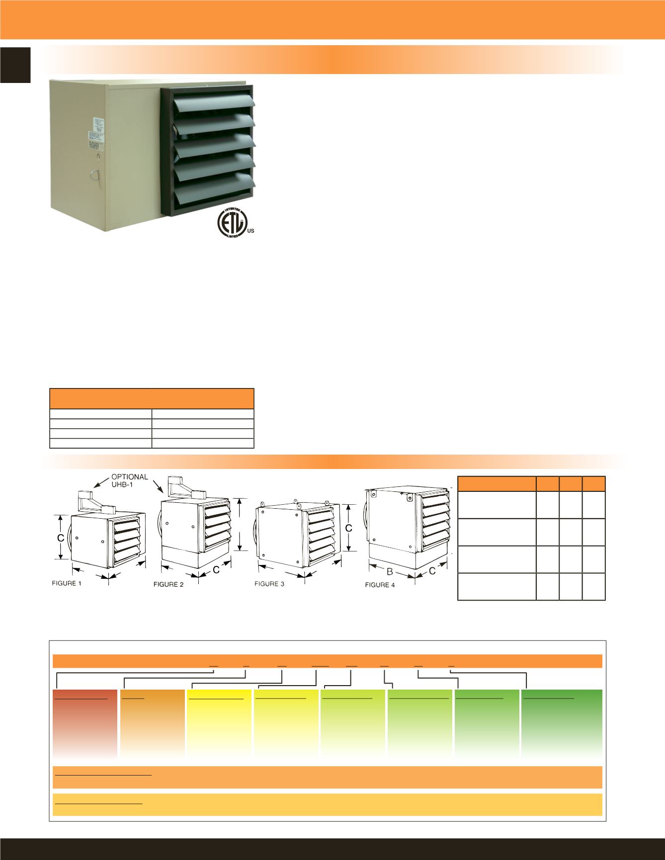
UH Series Horizontal Fan Forced Unit Heater
NOTE:
Louver assembly is square and mounted with
screws. Louver can be removed and repositioned for four
(4) directional air flow - left - right - up - down with the
heater in the horizontal position.
3.3 KW THROUGH 48 KW HORIZONTAL DISCHARGE SUSPENDED FAN FORCED UNIT HEATERS
AVAILABLE IN 1 OR 3 PHASE FOR ALL STANDARD VOLTAGES FROM 208V TO 480V.
Product Dimensions & Model Number Designation
Figures 3 & 4 shown with standard mounting tabs for units over 20 KW. Optional UHB-3 and UHB-4 wall brackets are available. 3.3 KW
thru 15 KW units can be mounted using 1/4” threaded rod. 20 KW thru 48 KW units can be mounted using 5/16” threaded rod.
CONSTRUCTION:
Heavy gauge welded steel cabinet with powder coated finish and control
compartment with a hinged and latched access door, simplifying wiring
installation & maintenance.
HEATING ELEMENT:
Circular copper clad steel sheath element with continuously brazed steel fins
formed to match the air delivery pattern of the fan blade.
OVERHEAT PROTECTION:
All units come equipped with automatic resetting type limit controls to de-
energize the heater should an over-temperature situation occur.
FAN and MOTOR:
Totally enclosed, single phase, permanently lubricated, thermally protected
motors with unit bearings on 3 KW - 10 KW models and sleeve bearings on 12.5
KW - 48 KW models - mounted with rubber insulators to minimize vibration and
noise. Fan assembly enclosed by a heavy gauge, close spaced, chrome plated
wire guard.
LOUVER ASSEMBLY:
Louvers are individually adjustable for directional control of air flow and the
entire assembly can be repositioned in the field from down flow to up flow or
left / right directional air flow.
TEMPERATURE CONTROLS:
20 KW through 48 KW units and all 480V have built in 24 Volt transformer
for low voltage remote thermostat application. 25 KW through 48 KW models
available in 2-stage on special order (consult factory).
INSTALLATION:
Unit Heaters can be mounted with the motor shaft from horizontal to downward
at 45° off horizontal. Pre-drilled holes and installed threaded nuts provided to
allow hanging by threaded rods - 1/4” for units up to 15 KW and 5/16” for 20
KW units and larger. Optional wall / ceiling mounting brackets are available for
all units.
FACTORY INSTALLED OPTIONS:
24 Volt transformer on 3 KW to 15KW units to
convert from line voltage to low voltage remote
thermostat operation.
Summer fan switch to operate the fan only.
Fan delay switch to purge all residual heat from the
unit after the heating element has cycled off.
• Powder coated epoxy finish for corrosive atmospheres.
Disconnect switch.
Manufactured in U.S.A.
Dimensions
A B C
Figure 1:
3.3, 5, 7.5, 10 KW
20” 11” 13”
Figure 2:
12.5, 15 KW
22” 11” 15”
Figure 3:
20, 25, 30 KW
24” 17” 17”
Figure 4:
40, 48 KW
26” 23” 19”
MAXIMUM RECOMMENDED MOUNTING
HEIGHT
3 - 10 KW
9 FT.
12 - 15 KW
10 FT.
20 - 30 KW
13 FT.
40 - 48 KW
16 FT.


