


 59 / 117

59
Ø .395 (TYP)
3
1
16
"
TYP
PEDESTAL
BASE
3"
7.500
6.15
2
15
16
7.500
6.15
3" MINIMUM
FINISHED FLOOR
2
7
16
"
"
12.0
Ø .395 (TYP)
3
1
16
"
TYP
PEDESTAL
BASE
3"
7.500
6.15
2
15
16
7.500
6.15
3" MINIMUM
FINISHED FLOOR
2
7
16
"
"
12.0
12.0
Ø .395 (TYP)
3
1
16
"
TYP
PEDESTAL
BASE
3"
7.500
6.15
2
15
16
7.500
6.15
3" MINIMUM
FINISHED FLOOR
2
7
16
"
"
12.0
12.0
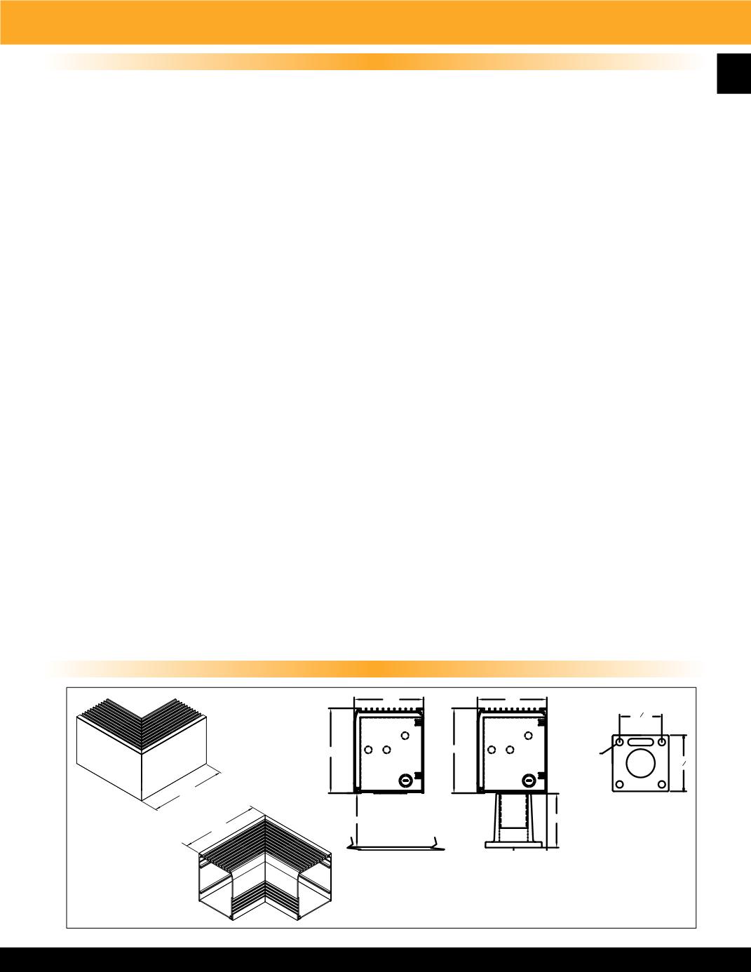
9300 Series - Radius Front Draft Barrier Heater
Product Dimensions
CABINET
9300 Series shall be constructed of 12 gauge extruded 6063 Aluminum heat treated to T5 hardness. The
uni-lock construction shall allow easy installation and access to back plate for wiring. The snap-fit front
cover makes installation and service very simple. Custom factory enclosures to 1/16 inch increments are
built for exact wall to wall fit up to 10 foot enclosure lengths. The 12 gauge back plate will have electrical
knockouts for incoming power on each end adjacent to junction box. Pedestal mounted units will have
incoming power connection through the pedestal on bottom of unit and will have smooth back for optional
finished back. The die punched front cover will have no screw heads or fasteners.
ELEMENTS
High mass sheathed element construction with Nickel-Chromium resistance wire embedded in compacted
efficient die-electric to ensure proper heat transfer. Aluminum fins mechanically bonded to stainless steel
tube allows for increased surface area and even heat transfer.
LIMIT CONTROLS
Manual reset hydraulic thermal overload covers full length of heating element and shuts down heater
when safe operating temperatures are exceeded.
WIRING
Wiring shall be in either end of the enclosure. Wiring can be in the junction box or optional control section
if additional controls are needed. Pedestal mounted units shall have 1-1/4” hole through the pedestal and
in the bottom of the enclosure for incoming power wiring. All heaters have a factory supplied built in
raceway for wiring from either end of the heater or for wiring of continuous heater connections.
CONTROLS
Optional controls include single or double pole thermostat and disconnect switch that are factory wired in
enclosed junction box on each end of heater enclosure.
If necessary, control section will add to heater
enclosure length
. The control section for other optional components or combinations of components will
have two options (6” or 12”) depending on controls required.
APPLICATION
The 9300 series is ETL listed for commercial or industrial applications on all units up to 750 Watts per
foot on all units. 3 Phase units have a minimum of 300 Watts per foot.
Product Specifications
INSIDE CORNER
SECTION
OUTSIDE CORNER
SECTION